 Telemetry
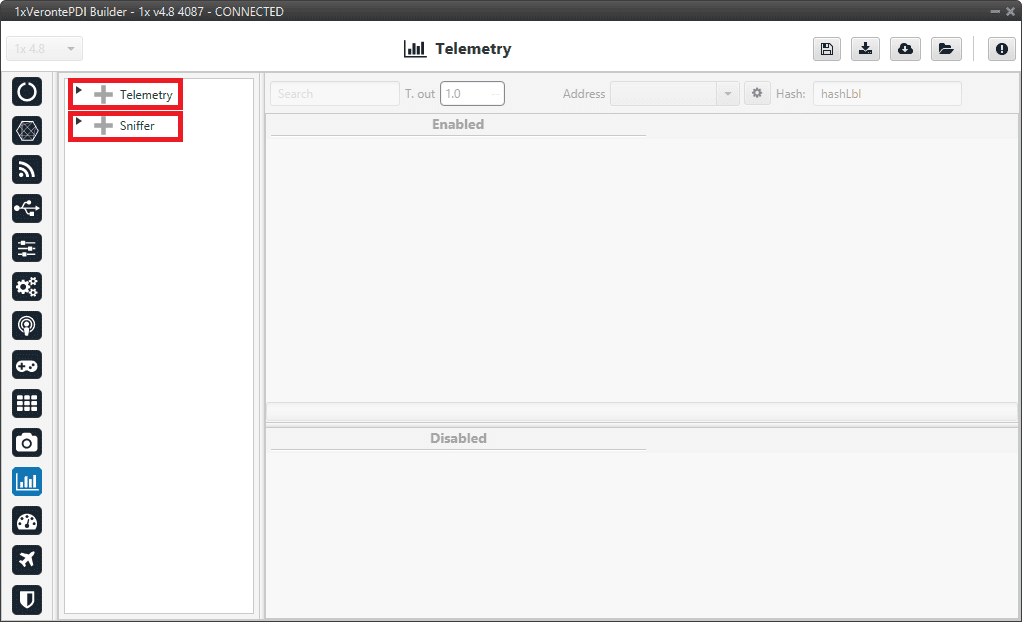
In this menu there are 2 options available: Telemetry and Sniffer.
Telemetry menu
Telemetry
Telemetry controls permit to configure data to be stored or transmitted on the system. There are 4 main items that can be configured within this panel:
Type |
Description |
|---|---|
Configures the variables to send throughout the data link channel. |
|
Sets the variables to be stored on system Log (on 1x SD Card). |
|
User Log for custom applications. |
|
Saves data at the maximum frequency available on the system. Recording time depends on the selected variables. |
Configuration display permits to enable the desired variables for each telemetry file and to set the maximum and minimum values together with precision for each one.
Data vectors
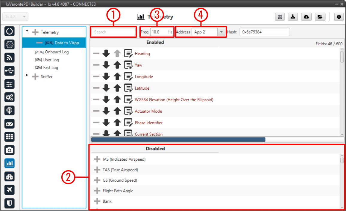
This panel contains the variables that Veronte Autopilots 1x send to the indicated address.
By default, 1x PDI Builder generates a Data vector to send telemetry from the configured Autopilot 1x to the Address 2 (Veronte applications). The variables indicated in red in a Data vector are required for correct operation.
Data vectors panel
In order to configure the variables sent, users have to:
Search: Search the desired variables into the Disabled panel.
Disabled: When the desired variables are found, add them to the Enabled panel by dragging and dropping them into it or simply by clicking on the
 button.
Freq: Specify the sending rate. 10 Hz usually works well, this frequency depends on the bandwidth of the radio.
Address: Enter the corresponding address, the following options are the most common: App 2 (Veronte applications address), Broadcast (all units on the network) and Veronte device address (to a specific unit). For more information on the available addresses, see List of addresses section of the 1x Software Manual.
Note
Hash parameter is not configurable, it is automatically calculated by the system based on the telemetry vector configured by the user.
It is a hexadecimal representation of the CRC of the fieldset.
1x PDI Builder allows the creation of more Data links by simply pressing in the ![]() icon next to ‘Telemetry’.
icon next to ‘Telemetry’.
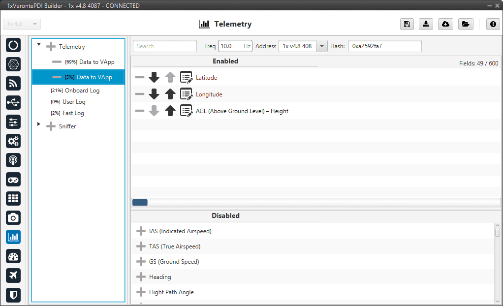
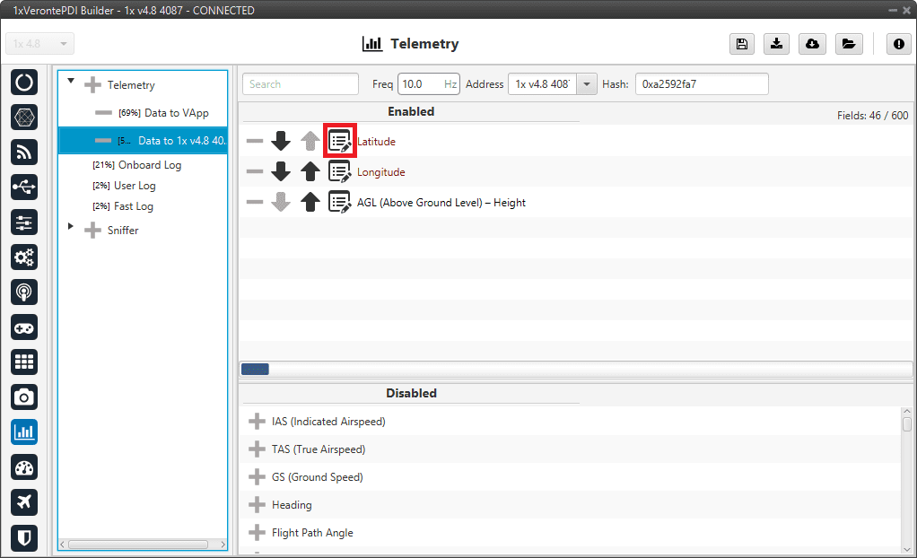
As an example, another possible data link could be set between the air and ground autopilots directly (without Veronte applications) and used to send the position of the UAV to the ground autopilot for the configuration of a tracker. This data link example is presented in the following figure.
Data vectors panel - Ground/Air units communication
If we consider this configuration as that of the air unit, this Autopilot 1x will send the Latitude, Longitude and AGL to the autopilot with address 1x v4.8 4087. The unit that receives the telemetry has to configure its sniffer (more information about this in the following section) in order to store the data.
Warning
If the number of variables enabled for telemetry communication are higher than the maximum supported by the system, the latest variables will not be sent, so they will display a zero value if shown in the workspace.
Note
It is possible to create more than one data link associated to the same receiver address, and they can also have different sending rates. It could be useful in case one of the data links is almost full.
Onboard Log
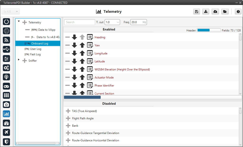
The Onboard Log determines the variables that are being stored on the autopilot SD Card. In this case, there are not sending/receiving units, so the only thing to configure here is the list of variables that will be saved on the autopilot internal memory for a further download and processing, as well as the writing frequency.
The log starts writing once the autopilot is turned on and does not stop logging until the autopilot is turned off.
Onboard Log panel
Warning
This is a circular log, which means that if the SD card memory is full, Veronte Autopilot 1x will delete the oldest logs automatically so it can continue logging.
Autopilot 1x has 2.5 GB of memory reserved for these logs. Hence the registered time can be calculated, for example:
If 10 variables are stored with 4 bytes each one, then each log will occupy 40 bytes
With a frequency of 10 Hz, the writing speed will be 400 bytes/s
\(\frac{2.5 \: GB}{400 \: bytes/s} = 6710886 \: s = 1864 \: h = 77.7 \: days\)
User Log
The user log contains the variables that are stored according to an automation created by the user.
Considering an example, in a photogrammetry mission it is important to record the aircraft location when the photo is taken, so a user log could be used to record a certain set of variables (position, speed, direction, …) each time a photo is taken.
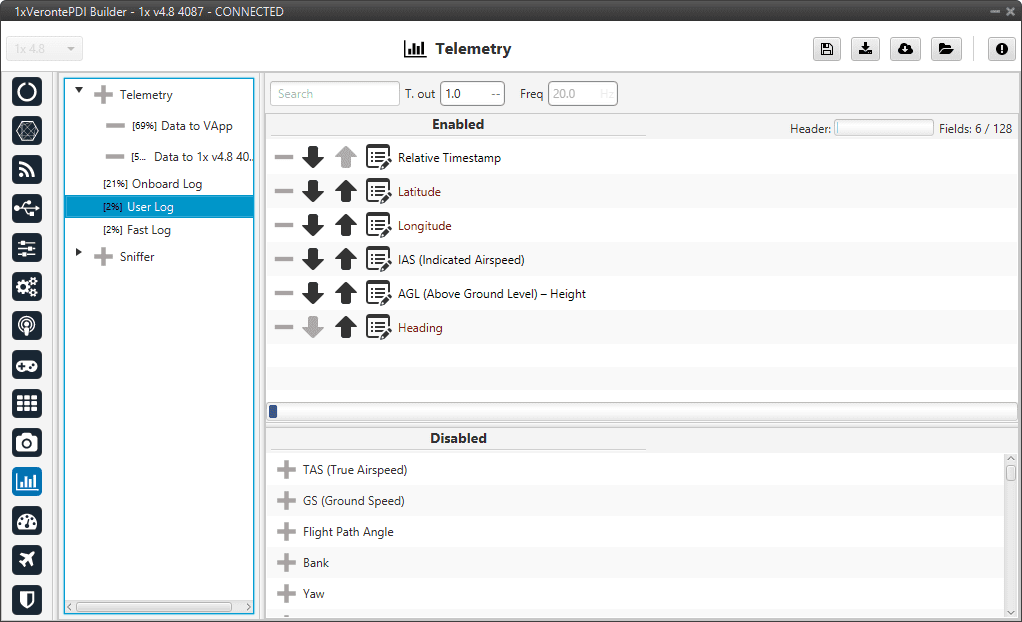
User Log panel
In order to create a User Log action where an entry is added to the log when a certain set of events are accomplished check the User Log action - Automations section of this manual.
Fast Log
The fast log store the specified variables at the maximum rate available on the system. This tool could be used to save information in an operation that happens extremely fast, such as missile launching. The time that this logging process lasts depends on the number of variables being saved.
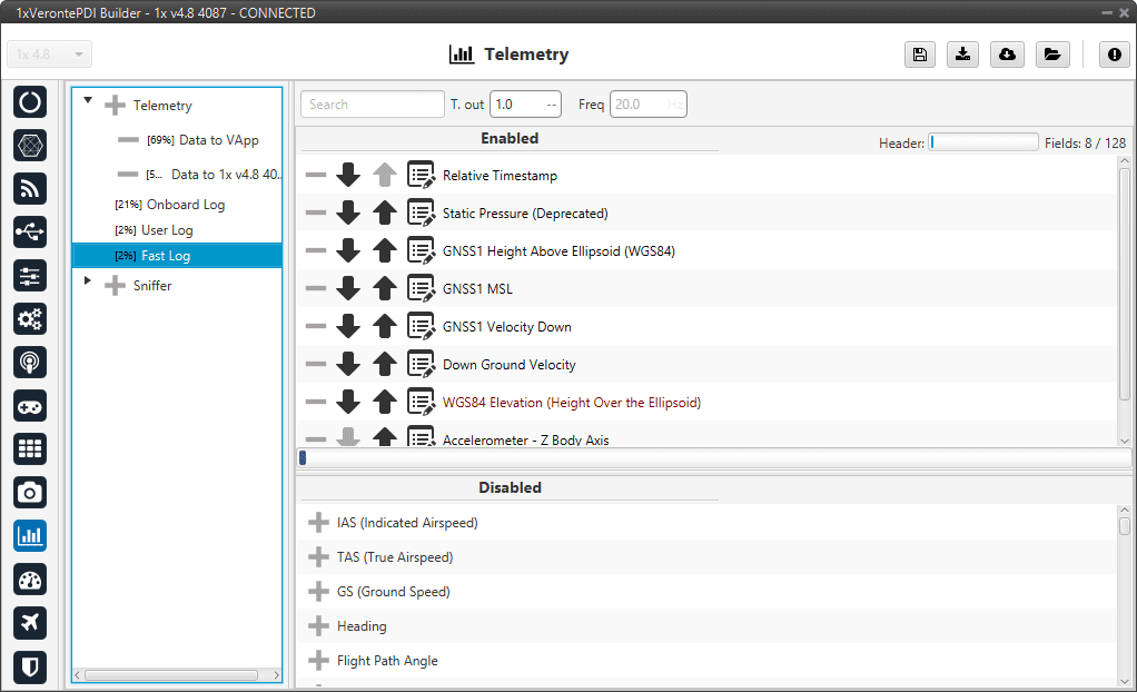
Fast Log panel
The Fast Log can be activated when the user wants, but must be done in Veronte Ops. For more information about Fast Log, check the Veronte Ops manual.
Important
The downloading of the information of an operation depends on how it has been stored, i.e depends on the type of log (data link, onboard, user or fast log).
For more information related to Onboard Log, User Log and Fast log downloading, visit Veronte FDR user manual.
Visit Veronte Link user manual for information about Data vectors downloading.
Besides, Autopilot 1x includes some compression tools that may be useful for increasing the amount of information transmitted in a certain bandwith or stored in a log. Each variable can be compressed separately in each log.
Compression options
There are different types of compression available:
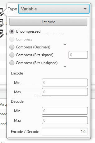
Compression options panel
Uncompressed: The variable is taken in its full length, with no value modification.
Compress (Bits signed): Specify the number of bits to be compressed to (negative values accepted). It is necessary that the user configures Encode/Decode options.
Compress (Bits unsigned): Specify the number of bits to be compressed to (no negative values accepted). It is necessary that the user configures Encode/Decode options.
Compress (Decimals): The variable is compressed according to the number of decimals specified and the range specified (max and min values). The resultant compression (number of bits) follows the relation \((max-min) \cdot 10^{decimals}\), which yields the encoding of the maximum value of the range (and the number of bits necessary for that). The range needs to be specified on the Encode - Min/Max field.
Encode/Decode: These values are used to apply a scaling factor after the transformation from binary to decimal value, or before the transformation from decimal to binary value.
In the example shown below, the Heading variable with 3 decimals will be compressed, so instead of using 32 bits, it will only require 19 bits.
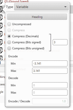
Compression example
Sniffer
This panel is used to establish telemetry communication between two Autopilots 1x or between a BCS unit and an Autopilot 1x. The autopilot being configured will “listen” the variables indicated in the window Enabled, from another autopilot whose address is indicated in Address. The sniffer is commonly used to make the aircraft listen the position of the ground station and the link quality.
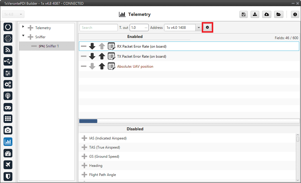
Sniffer panel
The source UAV, in this case, is the ground station (1x v4.8 4087), which communicates to the 1x air unit (address: 1x v4.0 1408) its position and some variables related to link quality (RX and TX Packet Error Rates).
The sniffer is configured so that the air autopilot has information about the state of the communications, and it could perform an action when the link is lost. The aerial platform also receives information about the ground station position, so it can perform a mission in relation to that point.
The Autopilot 1x unit that sends the data has to be configured as well (1x ground unit), in the Telemetry panel. That unit will send telemetry through a Data Link.
By clicking on the ![]() icon, the user can access the Mapping Variables configuration.
Here, the variables send by the ground unit are indicated in the columm From, and they are stored in the variables indicated in To for its later use by the 1x air unit.
icon, the user can access the Mapping Variables configuration.
Here, the variables send by the ground unit are indicated in the columm From, and they are stored in the variables indicated in To for its later use by the 1x air unit.
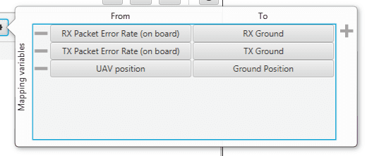
Mapping variables option
An example of the configuration required for communication between 1x ground and air units can be found in Data transmission between Veronte Autopilots 1x - Integration examples section of this manual.